In our newly released book “By Hand & Eye” we promised to post instructions build a sector. Jim put this together.
Making a Sector

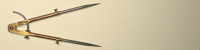
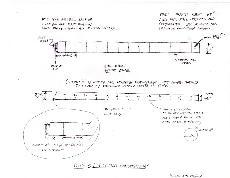
Select clear, straight-grained, light-colored stock such as maple. Produce sticks from 4/4 stock, tapering from about 7/8-in. at the base to ⅝-in. at the far end. This taper isn’t necessary, but it looks nice and it brings the balance point closer to where you generally are handling it in use. Your choice of length: I have one about 2-ft. long for scaling smaller projects and minor components and one about 3-ft. long for dealing with full furniture dimensions. The drawing shows the construction details and nuances—which include the fact that the pivot point of the sector’s legs is not the center of the hinge pin as you might expect, but the back of the hinge.


I really like how you can divide and multiply with these.
I made one from a 24″ single fold ruler and need to make a larger one to go with it.
Should have the new book today.
Two of the three guys I rode with to Amana bought the book there.
According to the illustration the centre point is at the back of the hinge pin rather than the back of the hinge. But why is it not at the expected place?
I was wondering about the center point too. The expected place to me is the center of the hinge pin. I’m starting to think it dosn’t matter.
I drew a sector on AutoCad and found it does matter where the start point is for the layout. I made one off the back of the pin and swung it 20 degrees and measured at the 1 went to the 10 and it was not ten times the distance. Then I did one with the start at the center of the pin and swung it open and had .250 at 1 and 2.500 at ten. Everything swings around the center of the pin; so to me that is where the layout starts. Easy to verify when you make one; put the sector on a 12″ rule at the 12 on the sector and 1 should be 1″ and 6 is 6″ and so on. If they dosn’t match up you need to move your start point.
Not sure how autocad indexes work, but in practice I find that the sticks actually do rotate from the back of the pin and not the center of the pin. So when I lay out the even divisions from the back of the pin I get more consistent readings from the sector—which I prove by setting the divider and stepping out..
I figured I was missing something; real world application . Thanks for the feedback Jim
Well I’m sorry, but I’m not so easily satisfied. I can’t see any reason why it wouldn’t rotate about the centre of the pin, and therefore need indexing from there. I guess I need to make myself a set/pair and see what results I get.
Of course, I laid awake last night for an hour thinking about all this….Try looking at it this way: Use a little tube of metal instead of a solid rod for the hinge pin. The tube has no center….so where does the center of rotation take place? In the real world, rather than the mathematic-based world of CAD, I’m pretty sure the hinge doesn’t care about the hinge center; it cares about what it’s knuckles are bearing against. That’s just my opinion, though—and if you don’t like it, I’ll probably have some others tomorrow morning!
The rotation takes place about the centre of the tube. Think of it this way, if you made it with a solid hinge pin and then drilled a hole down the centre of that pin, would you expect the centre of rotation to change?
If a hinge is properly made the knuckles should not bear on each other, all bearing surfaces should be on the outside of the hinge pin. Maybe you don’t have a properly made hinge?
Nick,
I made mine from a beat up Sweetheart Stanley rule 24″ single fold. Since there numbers started at the center of the pin thats where I started. I just went and checked (because I assumed and never did verify it) and when I have 6″ at the 6 I have 4″ at the 4 and so on. Thats my results; but I’m a rookie at sector building so the best thing is to try it and find out what works.
So Mark, I think you’re saying that yours works starting from the centre of the hinge pin. If so, that’s what I’d expect, and I think Jim needs to check that there isn’t something else going on with his. Just in case the index-from-the-back-of-the-pin thing doesn’t become one of those internet myths that just won’t die.
Or, to think of it another way, why would it choose to rotate about the back of the hinge pin rather than the front, left, right or any other random point around the pin’s circumference?
Please check your sector, find where the error is, and stop publishing mis-information. There’s more than enough of that on the internet already.
Nick,
Neither Jim nor anyone else on this string is publishing mis-information. Think of it like this. The center of the hinge pin is the center of rotation but not necessarily the actual intersection of our two reference planes (the inside surfaces of our arms). Another way to visualize this. If both arms were actually parallel, would the outside surfaces intersect at the center of the hinge pin? Of course not. The planes would intersect far behind the hinge in space. Likewise any slight misalignment will put our actual apex somewhere other than the true center of the hinge. On historic sectors used for scientific and navigation purposes, I’m sure great pains were taken to get all the reference surfaces spot on. For our purposes building furniture, we are not concerned with that level of precision.
George R. Walker
But George, in your O.P. you stated categorically “the fact that the pivot point of the sector’s legs is not the center of the hinge pin as you might expect, but the back of the hinge”. This is misleading at best. We might find that in practice the reference point is not at the centre of the hinge, as we ought to expect, but to state that the reference point IS at the back of the hinge pin, without qualifying it by saying that this is the case for Jim’s particular sector is misleading.
Quote: “not necessarily the actual intersection of our two reference planes (the inside surfaces of our arms)”
Here is the difference of what I drew on AutoCAD. The inside of my arms are parallel and touching and the center of the pin is at the end of the arm not behind it. That makes my arms intersect with the center of the pin.
The realization I just had is; it sounded like my drawing disproved Jim’s. When actually I drew my sector and proved to me it worked. So I was not comparing apples to apples. My apologies to you Jim.
Sincerely
Mark
OK, here’s the plane and simple fact’s (as opposed to the opinions I opined): If the distance between your focal point and the first division point aren’t equal, then the sector won’t be creating a series of Isosceles triangles and the derivations won’t work. If the first (zero to one) spacing is less than the rest, the divisions will fall short. (When using the sector to divide a space). So adjust accordingly—most simply by putting a little shim under the hinge plates, enough so that the division derivations come true. If the opposite occurs, sharpen up your block plane and trim a little bit off the ends of the legs.
This all seems a bit funny to me. If what we are trying to do is get away from building to print and moving toward ratios and what looks go to your eye, what does it matter if the sector is off by 1/16″ or so. If you are dividing a small pease in half you might notice, but for just about anything else the ratio still looks good. The pease looks good. No one will notice.
Timothy,
You have caught the sense of this approach. When I began using these proportional methods years ago, I was quite meticulous about using dividers with accuracy. As my confidence improved, I found myself gaging them by eye. I do think it’s important to take those initial steps with a sector and dividers to inform the eye. Side note – on many historic examples where one would expect artisans had enough experience to wing it, I’ve often found the proportions dead on.
George Walker
Pingback: Get Ready to Ratio | Baroque Pearls